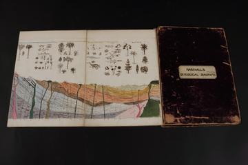
Marshall's Geological Diagrams
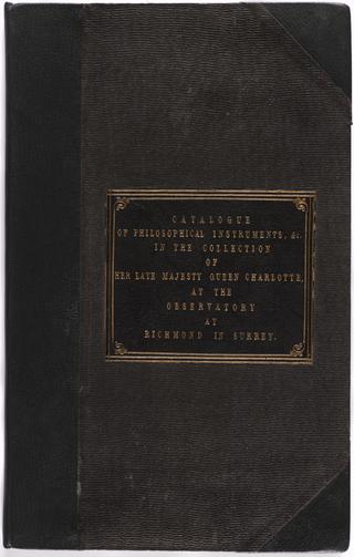
Manuscript entitled: "Catalogue of the Apparatus of Philosophical Instruments, in the Collection of Her Late Majesty Queen Charlotte, at the Observatory at Richmond in Surrey"

Catalogue of Useful Inventions for Cotton Spinners, Manufacturers and for all textile trades
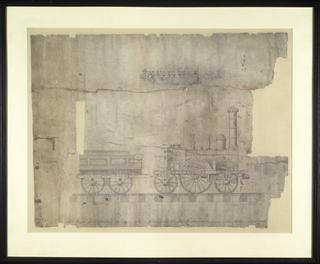
Drawing of St. Petersburg Railway Locomotive

Working Drawing for No 124 Locomotive
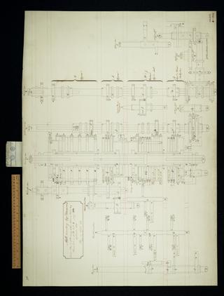
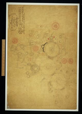
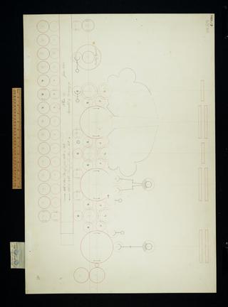
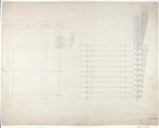
Mill counting apparatus. Consecutive elevation.
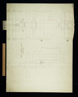
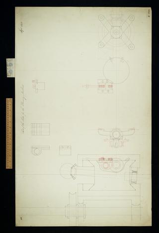
Sketch of drilling machine. Details.
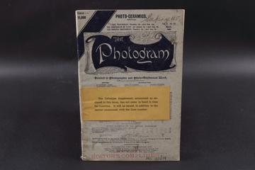
An edition of 'The Photogram' journal vol. 2 no. 17
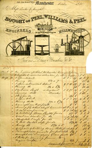
Invoice from Peel, Williams and Peel for a steam engine supplied to Messrs Coates and Wright

Working drawing for Nos 114, 115, 116
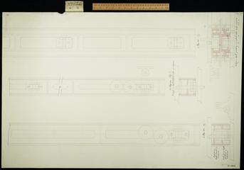
Figure 1. Plan, elevation and detail.
Untitled. This drawing is a cardboard model.
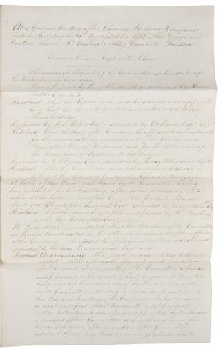
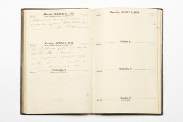
Handwritten Clarence Railway report
Railway Signal Volume 3 (1885)
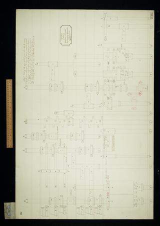
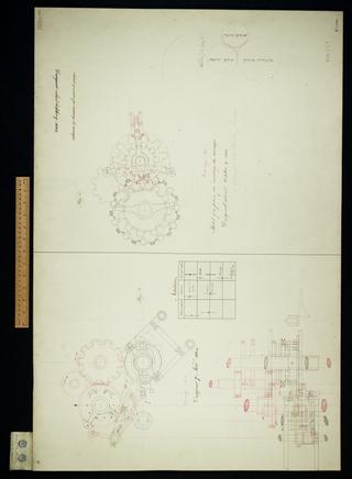
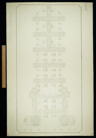
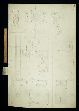
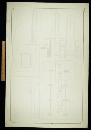
Plan of left half of middle group for General Plan 28.

The first drawing of the circular arrangement of the new engine
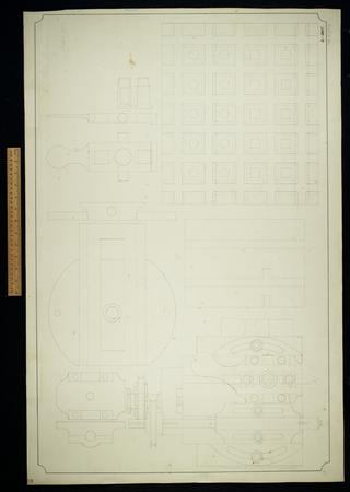
Small planing machine. Sheet 1.
Sketch of a plan for reserving the carriages.
Plan of mill, table wheels and carriage. Sheet 31.
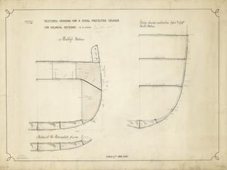
Drawing entitled 'Sectional Drawing for a Steel Protected Cruiser for Colonial Defence to be named'

General plan of the Analytical Engine, half size.
Notation of the Analytical Engine

Plan of operation and variable card counting apparatus. Suited to Plans 28 and 28a.
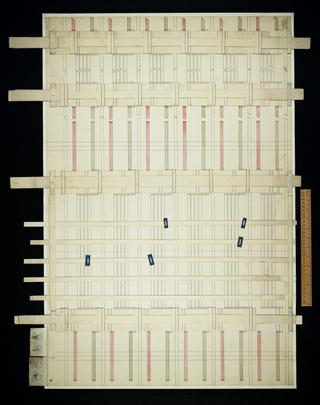
![Untitled. [Vertical positions of some of the wheels of Plan 28a. Notation 348 and 331 cycles]. Sheet 12 of 13.](https://coimages.sciencemuseumgroup.org.uk/221/221/large_thumbnail_bab_f_352_12_0001_vertical_positions_of_some_of_the_wheels_of_plan_28a_1845_oct.jpg)
Untitled. [Vertical positions of some of the wheels of Plan 28a. Notation 348 and 331 cycles]. Sheet 12 of 13.
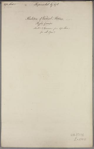
Skeleton of vertical motions for all operations. Right groups. Multiplication and division from 372 Sheet 1. Sheet 1 of 3.

Gearing et cetera of Sketch dated July 31 1835. Plan, once part of Drawing 22.

Parts of slide for the Planing machine. Plan, elevation
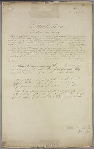
Multiplication. Sheet 1 of 4.
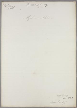
Algebraic addition. Sheet 1 of 2.
Difference Engine index of parts.
Sketches of the printing and stereotyping apparatus of the Analytical and Difference Engines. Superseded. Plan, elevation.

See designs dated 1834 November 27 and 1834 December 29.

First sketch of all the parts in plan of the right half to middle group of General Plan 28. Plan, elevation.

Parts of the slide for Planing machine. Plan, elevation.

Notation of periods for the centre group.
Plan 27. This was superseded by Drawing 93. Linear arrangement.

Plan and elevation of sundry parts in the upper cages of left half of middle group.
Parts of the slide for the Planing machine.
Algebraic addition of i k figures. Sheet 4 of 8.
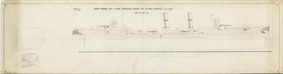
Drawing entitled 'Sheer Drawing for a Steel Protected Crusier for Colonial Defence to be named'

Addition No. 4. Carriage No 6. Elevation and plan.
Multiplication before the invention of multiplication by table. Sheet 2 of 2.
Store variable selectors. Superseding drawing No 2.

Motions of the stereotype frames
Platform raising apparatus. Sheet 33.

Verticals for approximative division. Sheet 2 of 4.

Verticals of the counting apparatus barrel number 1. Sheet 8 of 9.

Plan of picking-up sectors and a booklet of related notes